Recently, I was in deep research on how to make our own "Self Learning Universal Remote". So when I searched for the procedure of making this, first step I found is analyzing IR protocol,its frequency (time period),and also the combination of High and Low pulse for making a particular carrier frequency. And for measuring all these parameters, all the people either used DSO or some other hardware and software analyzer. But I didn't have any hardware or software for protocol analyzing except my Arduino MEGA board. Yeah!!!, now you can measure all the parameters of IR remote by your Arduino board only.


Steps for analyzing Frequency and Period
IR remote transmits the data by modulating it with a carrier frequency. Hence If we want to transmit the data through our arduino board, we must be aware of the carrier frequency of the remote. Hence analyzing Frequency and Time period becomes much important parameters.For analyzing the parameters, people used Oscilloscope and other hardware, software for this but what if we don't have anything except our Arduino Board. Lets see how we can analyze these parameters using Arduino.
Things Requied are:
Arduino Board.
Photodiode.
330 ohm Resistor.
Connect Photodiode and resistor to form a potential divider circuit.
Connect the junction point to pin 2 of your arduino board and upload this code. And press the button in front of your photodiode. You will get response like this.
This process is like trial and error method because sometimes Photodiode may give the unexpected result. So I will request you to follow this process 5-10 time to get the accurate result.
During my research, when I was decoding various IR remotes, I found that this data i.e. 12 us High,16 us Low and 35.7 kHz frequency is most common in all the remotes. But still you can confirm the parameters using this code.
Steps for analyzing Protocol
Different IR remotes follows different protocols. As I have also written blog for Samsung and NEC protocol previously, In that you can observe the difference. So after analyzing frequency and period, next step is to decode the data transmitted form that remote.
Things Requied are:
Arduino Board
TSOP IR receiver
Connect TSOP's signal pin to pin2 of your Arduino board. And upload this code to your board.
After uploading, open the serial monitor, It will show "Press the button once".
After that press the button of your remote ONLY ONCE. Because:
Case i)
In case of AC remotes, whenever we press the button it will transmit whole data of that button only once even if we have pressed the button for quite long time. Hence we must press the button only once. By pressing the button for the second time, the buffer in the code will be overflowed and the arduino will restart.
The Response we get when we press button of panasonic AC remote is as follows:

So the data of 439 bits is received when we press the button once. And yes this much amount of data is sent in every button. Now this data is in form of time duration, so we need to convert it into binary form to analyse it. For that we must be aware that which type of encoding is done in this. Every IR remote uses Pulse Distance Coding i.e. PDC for encoding the data. Hence whether the bit is 1 or 0 can be decided by the duration of the LOW time in signal. Duartion of HIGH time in signal will be constant around 500 us, so we need not to consider HIGH time whenever converting it into binary form.
If the duration of LOW time is around 300 to 400 us, than that bit is binary '0'
and
If the duration of LOW time is around 1200 to 1300 us, than that bit is binary '1'.
You can analyse the received data and recognize the START bit, STOP bit, binary '1' and binary '0' by below mentioned range.

So the received data will be around the mentioned range and with the help of this we can easily decode the received data. Lets decode the data which is received in the above image.

So this is the decoded data of my Panasonic AC. Than convert this data into 8 bit HEX code. Panasonic AC protocol consists of 8 bytes constant data and 19 bytes of other data which contains information of Temperature, Fan speed etc. In total there are 27 bytes of data, which is transmitted when we press single button of the remote.
You can search for different protocols for decoding binary '1' and binary '0'. But if you don't get any information, you can go for this logic,
first bit will be always start bit. and last bit will be always stop bit.
if low duration is greater than 1000 us , than it is binary '1'
and
if low duration is less than 1000 us , than it is binary '0'.
I don't know that this will work for all the appliances or not but mostly this will work.
Case ii)
In case of TV,Setup box, Radio remotes the data is transmitted continuously as long as the button is pressed. Even if the data of that particular remote is sent, it will repeatedly send the same data as long as the button is pressed.
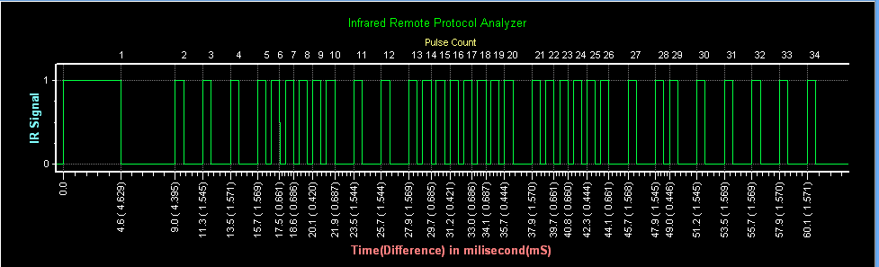
So, we need to press the button only once so that data is recorded only once. When I press the Remote of Radio which follows NEC protocol, the response I get is as follows,

So I received 75 bits of data which is not the true number in case of a NEC remote. Because NEC protocol sends only 34 bits(34*2=68 bits Here two is multiplied because for one bit we receive both High time and low time) of data including start bit and stop bit. But what if we don't know which protocol is this and how many data bits are their in that protocol??? In that case we need to look after the Stop bit. Now the question is how to recognize the stop bit. Stop bit of most of the protocols is a long duration of Low time. The duration is much longer as compared to the other bits in the signal, hence it easily gets highlighted in the serial monitor. The stop bit in this protocol is shown below,

In NEC protocol, the stop bit is 40,000 us long. Hence get easily noticed. So the exact data of the single button of NEC remote is upto this stop bit ( including stop bit).
And again, we can convert this data in its binary form by decoding the duration of Low time pulses.
Start bit High Time - 9050 - 9150 us
Start bit Low Time - 4450 - 4550 us
Data High Time - 450 - 650 us
Data Low Time '1' - 1650 - 1750 us
Data Low Time '0' - 450 - 550 us
Stop bit High Time - 450 - 650 us
Stop bit Low Time - around 40,000 us
So with this you can convert this duration into binary data. In NEC protocol data format is like
Start bit - Address byte - Inv. Address byte - Data byte - Inv Data byte - Stop bit.
So this is how you can analyze the protocol and parameters of different IR remotes by just using you arduino board. I tried my best to explain this topic in as simple way as possible, still if you have any doubt feel free to ask me by email or just comment below.
I have also made video on this topic, have a look.
You can download Codes from here.
#techiesms.