Thursday, 24 March 2016

Problem Solved :- ESP8266 with Software Serial ( Firmware Upgarding )

\


There was a problem faced by one my viewer in interfacing ESP8266 wifi module with Arduino UNO. In UNO, he was using Software Serial for communication with the module. Problem was that older version of ESP8266 was having default baud rate of 115200 and Software Serial doesn't work at this high baud rate. Software Serial perfectly works at 9600 baud rate. So the Solution is that, we need to change the baud rate of our ESP8266 wifi module.

One of the solution is that we can change the Baud Rate by giving AT command,

AT+CIOBAUD= Required Baud Rate

We can change the baud rate to 9600 by just writing AT+CIOBAUD=9600. And our problem is solved. But what I found is that, in my module this command was not at all working. I don't know the reason but it may be because of older firmware may not have this command defined in it. 

So first go for this step. If Your Baud Rate get changed, than no need to read this blog further. The response after entering this command will be something like this.

But If you face the similar problem which I have faced i.e. The command is not at all working on your module, than you need to go for firmware upgrading of your wifi module.
Firmware Upgrading
Firmware upgrading is not at all difficult. Just 2-3 steps and 2-3 minutes and you are done with it. First of all you need to download these necessary files before proceeding further.
After that, Open esp8266_flasher in that folder. And than select the bin file i.e. the firmware version you want to update, and also provide the COM port. It will be same port on which your Arduino is connected. Than click the download button.
It will take a minute while flashing your module. And after it complete its work, than you are ready to play with this module at 9600 Baud rate using Software Serial. And the good news is that, in this firmware, you can change the baud rate by the command AT+CIOBAUD to you required baud rate.
You can definitely watch my video in which I'm flashing my own module. I have made it in two Languages,
ENGLISH

HINDI

Files for upgrading ESP8266 firmware click here.
#techiesms

Sunday, 28 February 2016

MQTT + ESP8266 12e (Node MCU)


             MQTT(Message Queue Telemetry Transport) is a Client Server publish/subscribe messaging transport protocol. This protocol is widely used in the field of IoT for communication between Machine to Machine because of its following features ,
  •  light weight,
  • open, and
  • designed so as to be easy to implement.

Hence these features are Ideal for the IoT purpose as we need to transmit mostly status of one machine to another.It was originally developed by IBM and is now an open standard.


Note: If you are not familiar with Node MCU module, I'll request you to watch my video Getting started with Node MCU before going into MQTT.


Working of MQTT Transport Protocol.

This protocol is easy to implement and also very easy to understand. It basically comprises of one Broker and multiple clients where clients can be treated as our smart phone, sensors, etc. and they all communicate with the server which is known as Broker.

In this protocol, every client need to connect to any address of the broker which is known as the topic to be subscribed in MQTT. In single broker there can be multiple topics and clients can also subscribe to multiple topics of the same broker.

First lets see this process in block diagram which will be easy for you to understand.


So basically here we have one broker and 3 clients subscribed to the topic “temperature”. 


So as soon as any of the client(Temperature Sensor) publishes or updates the value of Temperature to the broker, than all the clients(Smart Phone) subscribed to that topic will receive the value of temperature updated.
That’s it.

We can do a lot with this simple protocol. We can even subscribe to the topics of any other person if we know the username and password of the broker.

Implementation 


We will be making a project on "Controlling Home Appliances through Internet via MQTT". I will be demonstrating this by controlling Radio and Light of my room. 

Things required for making this:

  • ESP8266 12e development Board
  • 6V Relay x2
  • BC547 Transistor x2
  • 330 ohm Resistor x2
  • Connecting wires
  • BreadBoard


Broker
First of all we will need a MQTT broker. There are many broker for MQTT but I have used Adafruit MQTT broker. Its quite simple and its UI is also great. You will love to use that broker. For using Adafruit MQTT broker, first of all you need to make an account on Adafruit.io. Fill up the basic details and you are ready to use that broker.

Than goto your dashboard. My dashboard is like this.


There many options on the right corner of the page to edit the blocks, add new blocks,get the key,etc.

Now we will start with making a new button on the dashboard. For that click on the 2nd button i.e."Create a New block". It will show this window.


There are number of blocks to be added in this window like toggle button, push button, slider etc. In our project we will be using the first block i.e. toggle button. Click on create button and you will get following options.


Than you have to provide feed name which should be unique because this feed name is nothing but the topic which clients will be subscribing. I have given name of the feed as onoff. Than click the create button. And click on the choose button front of your feed name. Than click on the next step.


Than we need to provide what string to be sent when the button is ON and OFF. So, I have wriiten 1 for ON and 0 for OFF.


That's it. You are done with the broker side. No complexity, nothing. Only simple and great UI and that's why I like adafruit broker. You can even drag and resize the block according to your need.


Account holder at Adafruit IO will have their unique key which is also called as password for the subscription. You can get your key by clicking on the third button on the right corner. It is a key shaped icon on the button.


Client

We will be using two clients in our project first is the ESP866 12e development board and another is our Smart Phone. First of all you need to download library for MQTT  client by Adafruit. You can download the library from here.

Now open example in your Arduino IDE named "mqtt_esp8266". Just change the ssid name, password for internet access and also provide your broker username and password(AIO key). And than just upload the program because in the example sketch, they have already subscribed to the topic onoff so no need to change anything in this. Than open serial monitor and your adafruit dashboard side by side.


As MQTT is very light weight, the response we can observe is around in couple of milliseconds. It's really fast!!! As you can see in the Serial monitor, whenever I toggle the switch it shows the response like "GOT 1" or "GOT 0". And side by side it is also publishing value of counter on the topic named photocell. 

Another Client is our smart phone. For that you need to download an app of MQTT client. I have downloaded this app in my android device. Just provide 4 details.

Broker URL, here it is (io.adafruit.com)
Port, (1883)
Username ( username you have registered while making your account)
Password (Key which you can get by clicking the key icon on your dashboard)

After filling this details just subscribe to any of the topic and send either 0 or 1 to turn the button on or off. And yeah!!!!, now you can toggle the button from anywhere in the planet earth as long as you are in coverage area of your Internet service provider.


#techiesms

Tuesday, 16 February 2016

Analyze any IR protocol with just you Arduino board

               Recently, I was in deep research on how to make our own "Self Learning Universal Remote". So when I searched for the procedure of making this, first step I found is analyzing IR protocol,its frequency (time period),and also the combination of High and Low pulse for making a particular carrier frequency. And for measuring all these parameters, all the people either used DSO or some other hardware and software analyzer. But I didn't have any hardware or software for protocol analyzing except my Arduino MEGA board. Yeah!!!, now you can measure all the parameters of IR remote by your Arduino board only.


Steps for analyzing Frequency and Period

IR remote transmits the data by modulating it with a carrier frequency. Hence If we want to transmit the data through our arduino board, we must be aware of the carrier frequency of the remote. Hence analyzing Frequency and Time period becomes much important parameters.For analyzing the parameters,  people used Oscilloscope and other hardware, software for this but what if we don't have anything except our Arduino Board. Lets see how we can analyze these parameters using Arduino.

Things Requied are:

Arduino Board.
Photodiode.
330 ohm Resistor.

Connect Photodiode and resistor to form a potential divider circuit.


Connect the junction point to pin 2 of your arduino board and upload this code. And press the button in front of your photodiode. You will get response like this.


This process is like trial and error method because sometimes Photodiode may give the unexpected result. So I will request you to follow this process 5-10 time to get the accurate result. 

During my research, when I was decoding various IR remotes, I found that this data i.e. 12 us High,16 us Low and 35.7 kHz frequency is most common in all the remotes. But still you can confirm the parameters using this code.


Steps for analyzing Protocol

Different IR remotes follows different protocols. As I have also written blog for Samsung and NEC protocol previously, In that you can observe the difference. So after analyzing frequency and period, next step is to decode the data transmitted form that remote. 

Things Requied are:

Arduino Board
TSOP IR receiver

Connect TSOP's signal pin to pin2 of your Arduino board. And upload this code to your board.
After uploading, open the serial monitor, It will show "Press the button once".

After that press the button of your remote ONLY ONCE. Because:

Case i)

In case of AC remotes, whenever we press the button it will transmit whole data of that button only once even if we have pressed the button for quite long time. Hence we must press the button only once. By pressing the button for the second time, the buffer in the code will be overflowed and the arduino will restart.

The Response we get when we press button of panasonic AC remote is as follows:


So the data of 439 bits is received when we press the button once. And yes this much amount of data is sent in every button. Now this data is in form of time duration, so we need to convert it into binary form to analyse it. For that we must be aware that which type of encoding is done in this. Every IR remote uses Pulse Distance Coding i.e. PDC for encoding the data. Hence whether the bit is 1 or 0 can be decided by the duration of the LOW time in signal. Duartion of HIGH time in signal will be constant around 500 us, so we need not to consider HIGH time whenever converting it into binary form.

If the duration of LOW time is around 300 to 400 us, than that bit is binary '0'
and
If the duration of LOW time is around 1200 to 1300 us, than that bit is binary '1'.

You can analyse the received data and recognize the START bit, STOP bit, binary '1' and binary '0' by below mentioned range.


So the received data will be around the mentioned range and with the help of this we can easily decode the received data. Lets decode the data which is received in the above image.

So this is the decoded data of my Panasonic AC. Than convert this data into 8 bit HEX code. Panasonic AC protocol consists of 8 bytes constant data and 19 bytes of other data which contains information of Temperature, Fan speed etc. In total there are 27 bytes of data, which is transmitted when we press single button of the remote.

You can search for different protocols for decoding binary '1' and binary '0'. But if you don't get any information, you can go for this logic,

first bit will be always start bit. and last bit will be always stop bit.
if low duration is greater than 1000 us , than it is binary '1'
and
if low duration is less than 1000 us , than it is binary '0'.

I don't know that this will work for all the appliances or not but mostly this will work.


Case ii)

In case of TV,Setup box, Radio remotes the data is transmitted continuously as long as the button is pressed. Even if the data of that particular remote is sent, it will repeatedly send the same data as long as the button is pressed. 

So, we need to press the button only once so that data is recorded only once. When I press the Remote of Radio which follows NEC protocol, the response I get is as follows,


So I received 75 bits of data which is not the true number in case of a NEC remote. Because NEC protocol sends only 34 bits(34*2=68 bits  Here two is multiplied because for one bit we receive both High time and low time) of data including start bit and stop bit. But what if we don't know which protocol is this and how many data bits are their in that protocol??? In that case we need to look after the Stop bit. Now the question is how to recognize the stop bit. Stop bit of most of the protocols is a long duration of Low time. The duration is much longer as compared to the other bits in the signal, hence it easily gets highlighted in the serial monitor. The stop bit in this protocol is shown below,


In NEC protocol, the stop bit is 40,000 us long. Hence get easily noticed. So the exact data of the single button of NEC remote is upto this stop bit ( including stop bit).

And again, we can convert this data in its binary form by decoding the duration of Low time pulses.

Start bit High Time - 9050 - 9150 us
Start bit Low Time - 4450 - 4550 us
Data High Time -     450 - 650 us
Data Low Time '1' -   1650 - 1750 us
Data Low Time '0' -   450 - 550 us
Stop bit High Time - 450 - 650 us
Stop bit Low Time - around 40,000 us 

So with this you can convert this duration into binary data. In NEC protocol data format is like 
Start bit - Address byte - Inv. Address byte - Data byte - Inv Data byte - Stop bit.

So this is how you can analyze the protocol and parameters of different IR remotes by just using you arduino board. I tried my best to explain this topic in as simple way as possible, still if you have any doubt feel free to ask me by email or just comment below.

I have also made video on this topic, have a look.

You can download Codes from here.

#techiesms.


Monday, 8 February 2016

Fetching Data from any Website

             This Project idea struck in my mind during the time of IPL(Indian Premier League) when we used to be in our class attending lecture and we guys are so much curious about the live status of the match. At that time I thought of a small screen on which we can get regular updates of the match. And the Research Begins.........

            Visualizing it in block diagram wise, first of all we need search for a website on which we can get the live updates of whatever we want like live stock prices,current time, current temperature,YouTube Views,likes  and many more. Later we need to fetch the data from the server of that website and make an API(Application Program Interface). API serves the purpose of getting access to only those data which we are in need of from all the data available on the server.Suppose we need only number of views of our video uploaded on YouTube. So we need a interface which rather than requesting the whole HTML page, requests only number of Views of our video. Than we will give a GET request as we want to fetch the data from the server. All this task will be done through Thingspeak.com . A great website for your IoT based projects.

             In thingspeak.com, we will get our required API.  To test the API just request the link provided by thingspeak(On the right side of the page) in your browser than you will only get the data for what you requested.


In this Image,  I have created an API of number of views of my YouTube Video. Method I selected is GET as we want to fetch the data and HTTP version is 1.0. Than I Inserted URL of the page and for the last row (Parse String) you need to follow following steps.


Now paste that XPath into parse string row and thats it save it and API will automatically get generated. Test it by pasting that link into your browser. Than it will show something like this.


This is all about to pick up the right data.But what if we want to make project based on this. To make this data more useful you will require Arduino, LCD and the most amazing thing ESP8266 ( WiFi Module).


ESP8266(WiFi module)

             This is an absolutely amazing thing which will help your controller to communicate to the virtual world.And it is very easy to use. It has a on chip controller and we can communicate with this WiFi Module via AT Commands.Here is the list of all AT Commands.


If you are using Arduino Mega than you can use Serial1(RX1 and TX1) and Upload MultiSerialMega code into you board and change the baud rate to 115200 and you are ready to use WiFi Module. Just use all this AT commands once so that it will get easier to deal with this module further.

Steps for fetching data through API

Step 1:

Reset the WiFi module :- AT+RST
Set the mode to 3:- AT+CWMODE=3
Join any WiFi network :- AT+CWJAP = "SSID_Name","SSID_Password"

Step 2:

After connecting to the WiFi network, we need to establish a TCP connection to communicate with servers via port 80. To establish a connection, the AT command is,

AT+CIPSTART = "TCP","api.thingspeak.com",80

In our project, we are using API generated from Thingspeak.com so we have written the host server name as api.thingspeak.com. 

After this command we need to provide that how many number of characters we need to request. For this the command is,

AT+CIPSEND=90

in our case the number of characters are constant i.e. 90. Because different APIs from thingspeak.com will have different api key rest of all the things will remain same.

Step 3

After that we need to request the api generated from thingspeak.com. As we want to get the data from the server, we will send a GET request. And the sequence goes like,

GET /apps/thinghttp/send_request?api_key=XXXXXXXXXXXXXXXX 
Host: api.thingspeak.com

So whenever you make a new api, just change the key and leave rest of the things as it is.

Step 4

After following all the three steps, you will get the data in response. But many times the we need to filter the required data from the response we get.So for that we need to filter the required data form the response. And this can be done easily through some of the commands of String which I have mentioned in the code.


             This is all you need to know if you want to  fetch the data from internet and use it further for your project. I have made one sample project so that it becomes easier for you to understand the whole concept. This is the same project on which I have recorded the video i.e. fetching data from website and display it on your touchscreen. 

             If you don't have touchscreen module, just filter out the required data and analyse the response from the server on your serial monitor.

If the concept is still not cleared than have a look to my video tutorial for this whole procedure. And I have also shared the Arduino code for the same.


#techiesms


Saturday, 30 January 2016

Getting Started with WiFi Module(ESP8266)

In this section we will see how to use this tiny little still most useful module ESP8266. Main reason for the popularity of this module is I think its price and its features. It is easily and cheaply available in the market for just ₹ 250-300.
The ESP8266 is a micro-controller from Chinese manufacturer Espressif that includes Wi-Fi capability.This small board allows micro-controllers to connect to a WiFi network. This little module can work in station mode, access point mode or both. Each ESP8266 module comes pre-programmed with an AT command set firmware.

First of all lets see the pins of this module. We can communicate with this module via serially. We can use either USB to TTL converter or you can use your Arduino board as I have used.

Pins of ESP8266 module 


Things Required are:


  1. BreadBoard
  2. Arduino Board
  3. ESP8266 WiFi module
  4. LD33CV IC ( 3.3V regulator IC)
  5. Resistors (1k & 2.2k)
  6. Some connecting wires

STEP - 1


As this module is not breadboard friendly, you need to follow the steps shown below before using this module.


Cut a piece of prefboard, and first solder female connector as shown in the fig below.


After that, solder male headers on the opposite side of the prefboard. It would look something like this.


Now attach the module on to the converter.


With this, it can be easily connected on to the breadboard.


STEP-2


Note: This module strictly works on 3.3V do not give 5V supply to this module.

As this module works on 3.3V we need to use a 3.3V regulator IC (LD33CV) or you can also use 3.3V pin from your arduino board. Even the Tx pin of arduino will provide 5V signal to the module. Hence we need to step down the signal to around 3.3V before feeding it to the module.

Connection of all this things is shown in the fig. below.
I have used the Rx1 and Tx1 of Arduino MEGA board. But you can even use the Rx and Tx pins. I have used this pins beacuse in my further WiFi projects, I have used TFT touch screen module, hence we won't be able to use pin 0 and 1.

Open Arduino software and open Multi Serial Mega example and change the baud rate to 115200 and upload the code. Change the baud rate in serial monitor to 115200 and the mode to Both NL & CR.

STEP-3

Now communicate with this module by sending the AT commands in the Serial monitor and play with this module.List of  AT commands are given in the PDF whose link is mentioned below.


I have also made a video on "Getting Started with ESP8266, As simple as possible"                                                                                


Datasheet of ESP8266
   AT Commands 


#techiesms

Monday, 25 January 2016

IR Protocol Decoding and Transmiting through Arduino

In this blog, I will described various IR protocols adopted by different companies and will go in detail about 2 protocols. One is the most commonly used NEC protocol and another is the Samsung protocol. Why??? Because I have Samsung TV which uses its own protocol and a GTPL setup box, which uses NEC protocol as simple as that.


Source: Wikipedia


Different Companies uses their own protocols for eg. we have protocols like Samsung, LG, RC5/RC6 by Philips,and the most commonly used protocol NEC protocol.


Lets discuss the two protocols in detail.


SAMSUNG Protocol


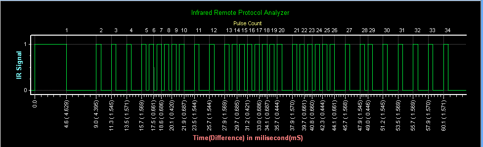
Samsung protocol goes in sequence like a start bit,8 bit address,8 bit address,8 bit data and inverse of 8 bit data. In total there are 32 bits after start bit containing address and data.Start bit of this goes like HIGH for 4.5 ms and LOW for 4.5 ms. Followed by this start bit, address and data bits are transmitted. Frequency of transmission is around 38 kHz. To be precise it is 37.9 kHz. Level HIGH and level LOW is decided based on the duration on the low level of the signal. Logic 1 and 0 is decoded like this:


IR signal of samsung protocol will look something like this, and its sequence goes like

start bit - Address - Address - Data - Inverse Data - stop bit

start bit- 11100000 11100000 00100000 11011111-stop bit
This signal contains address - 11100000   data - 00100000.


NEC Protocol


NEC protocol is most commonly used for IR communication. Its frequency of transmission is around 38kHz. The difference in samsung protocol and NEC protocol can be easily identified by the start bit. Samsung has 4.5 ms mark and 4.5 ms space while NEC protocol have a start bit of 9 ms mark and 4.5 ms space.


Another difference between samsung protocol and NEC protocol is that NEC protocol contains Address and inverse of Address after that while samsung protocol repeats the address twice. Logic 1 and 0 of this protocol is same as that of samsung protocol.


Decoding and Transmitting Through Arduino


Decoding this signal using arduino is very simple. We will use pulseIn() function to read the duration of the pulse and accordingly decide weather the received bit is high or low.

Things Required;

1. Arduino Board
2. TSOP IR reciever
3. IR LED 

TSOP IR reciever will give digital output of the IR data received on 38 kHz frequency. By default, it will give digital 1. 
Note: This receiver will give the inverse output. i.e. If IR signal transmitted is 0, than TSOP reciever will give output 1.

DECODING:

STEP 1:

First of all we will wait for the start bit of the signal. After that we will turn ON the led for indicating that IR signal is received.(This is the example of decoding a NEC IR signal).


STEP 2:

Than we will check that whether the received data is logic 1 or 0 and we will store that 32 bit data in a boolean array.


STEP 3:

Than we will separate address and data from this array. Now as we know that in NEC protocol the first 8 bits are the address and 17th to 24th bit are the data. Hence we will sort it accordingly.


Thats it. We have decoded the NEC protocol. Now lets see how to transmit it via IR LED.

TRANSMITTING

STEP 1:

First of all we will make a array of 32 bit and store the address in first 8 bits and the inverse of the address in another 8 bits. I am fetching the address value in integer from EEPROM.


STEP 2:

Than we will store the data and inverse of the data in the remaining 16 bits of the array.

STEP 3:

Than we will transmit this 32 bit data along with start bit and stop bit.Start bit of NEC protocol is HIGH for 9 ms and LOW for 4.5 ms. Here burst is the function which will send the HIGH signal at 38kHz frequency.


Burst is the function which will send pulses at 38 kHz frequency. Value of the burst signal may vary because of the time delay of the instructions. So I have tried by different divisions, and finally the transmitter was working when I divided the HIGH time delay by 38 for which actual dividend by calculation comes out to be 26 (9 us+17 us).

That's it. You are done with the decoding and transmission. You can even store the codes of the remote sequentially in the EEPROM and than transmit the code by fetching the data from EEPROM.
The pics in this blog are example of NEC protocol. I have attached link of a code for decoding and transmission  of code of Samsung protocol.

Further I am trying to make a self learning universal remote control which can simply copy the code into the memory and can be able to transmit the same signal. So that the issue of different protocols will be nullified.If any one have any idea regarding learning remote, do mail me.


Arduino Files:

Samsung Protocol Decoder
Remote Transmitter


#techiesms